
Inputs monitor door contacts, request-to-exit (REX) devices, tamper switches and other field devices wired to a Mercury controller or sub-panel, including MR16IN boards.
1. Open an Input
- Go to Hardware › ACUs and click the controller's name.
- On the Topology tab, click the board the device is wired to.
- Click an input, such as I1 to I8.
Note: Before making changes, confirm the board shows MATCHED. This means the configuration matches the physical hardware. The number of reader ports, inputs and outputs depends on the board model.
Input settings are on five tabs: Type, Wiring, Link, Live and Advanced.
2. Type Tab
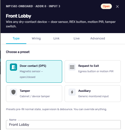
| Preset | Use it for |
|---|---|
| Door contact (DPS) | A door position switch. Detects door opened, closed, forced open and held open. |
| Request to Exit | An exit button or motion sensor. Unlocks the door or suppresses the forced-door alarm on an approved exit. |
| Tamper | Enclosure, controller or reader tamper switches. |
| Auxiliary | Anything else: emergency buttons, equipment contacts, interlocks, sensors. |
Presets pre-fill the normal state, supervision and debounce. You can change any of them. Enter a Name that says where and what the device is, such as "Rear Entrance Door Contact" or "Panel Enclosure Tamper".
3. Wiring Tab
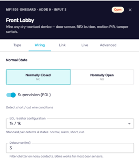
- Normally Closed (NC) or Normally Open (NO): must match the device. Door contacts are usually NC.
- Supervision (EOL): turn on if end-of-line resistors are installed. The controller can then tell normal, active, short and cut-wire conditions apart. Choose the EOL resistor configuration that matches the resistors at the device: 1k / 1k, 1k / 2k, 2.2k / 2.2k, 4.7k / 4.7k or Custom.
- Debounce (ms): how long the input must stay stable before a change counts. Keep the default unless the input chatters.
4. Link Tab
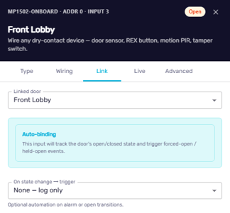
- Linked door: the door the device is on. Linking a door contact lets Alocity track door opened, closed, forced open, held open and restored automatically.
- On state change → trigger: None — log only, Generate event, Send notification or Run action: Lockdown site. Door contacts linked to a door usually need None, because the door handles their events.
IMPORTANT: Use Run action: Lockdown site only for a dedicated lockdown button, and test it with the site's security lead.
5. Live Tab
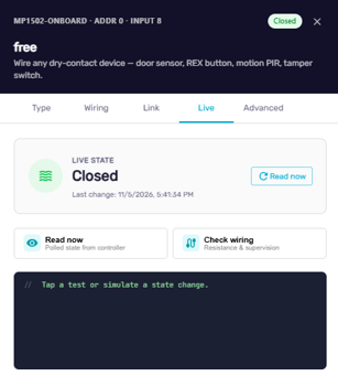
- Live state: the input's current condition, such as open, closed or alarm.
- Read now: polls the input. Open and close the door to confirm the state changes.
- Check wiring: tests for open circuits, shorts, wrong resistor values and a wrong NC/NO setting.
6. Advanced Tab
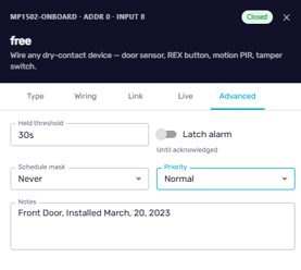
- Held threshold: how long the input can stay active before a held alarm, for example 30 seconds for a door held open.
- Latch alarm: keeps the alarm active until someone acknowledges it.
- Schedule mask: Never (always monitored), a schedule such as Business Hours, or Custom.
- Priority: Low, Normal, High or Critical.
- Notes: location, resistor values, cable IDs or troubleshooting history.
7. Save and Verify
- Check the type, name, NC/NO and supervision settings.
- Link the input to the correct door.
- Click Save. (Release frees the input from its current assignment.) [VERIFY: confirm what Release does]
- On the Live tab, open and close the door or press the button to confirm the state changes.
For questions or assistance, please contact your account manager or email support@alocity.com.